[Next: Step 2 - Laying out the Board >>]
Parts
To begin with, you'll need to create seven sensor circuits. The total parts
list includes
* The Sharp GP1S525 now seems to be sold out, but the
GP1S525VJ00F
seems to be a suitable replacement and is available
from digikey.
Sensor Circuit
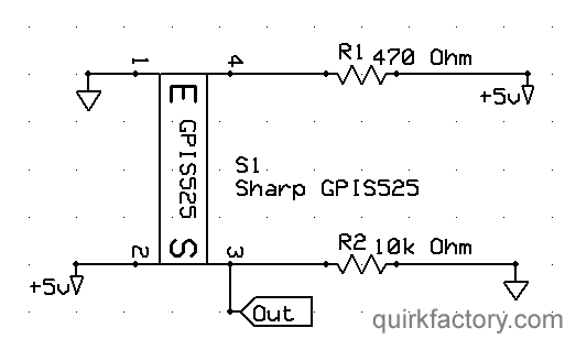
 This picture shows the detail of the sensor circuits.
Note the alignment of the emitter and sensor parts of the
Sharp GP1S525
which are are labeled on its case.
This picture shows the detail of the sensor circuits.
Note the alignment of the emitter and sensor parts of the
Sharp GP1S525
which are are labeled on its case.
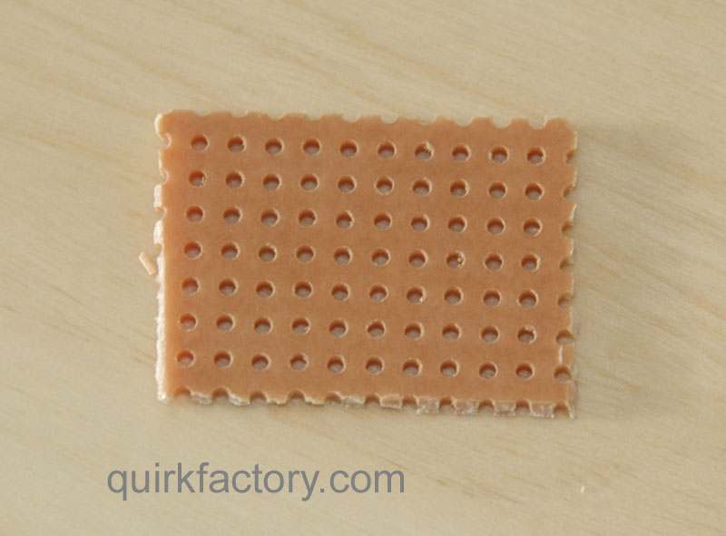
 These smallish circuits can be mass-produced on a printed circuit board
(which can then be cut into pieces), or else they can be constructed on
small protoboards like the one shown here.
These smallish circuits can be mass-produced on a printed circuit board
(which can then be cut into pieces), or else they can be constructed on
small protoboards like the one shown here.
Assembly
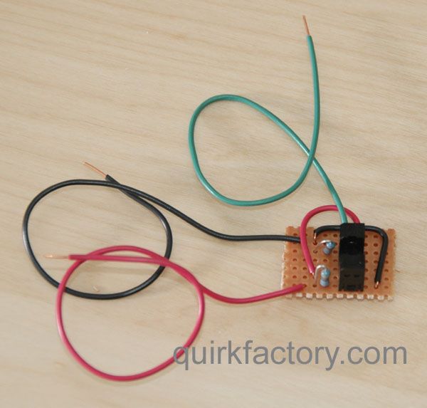
 If constructing the sensors by hand on proto board,
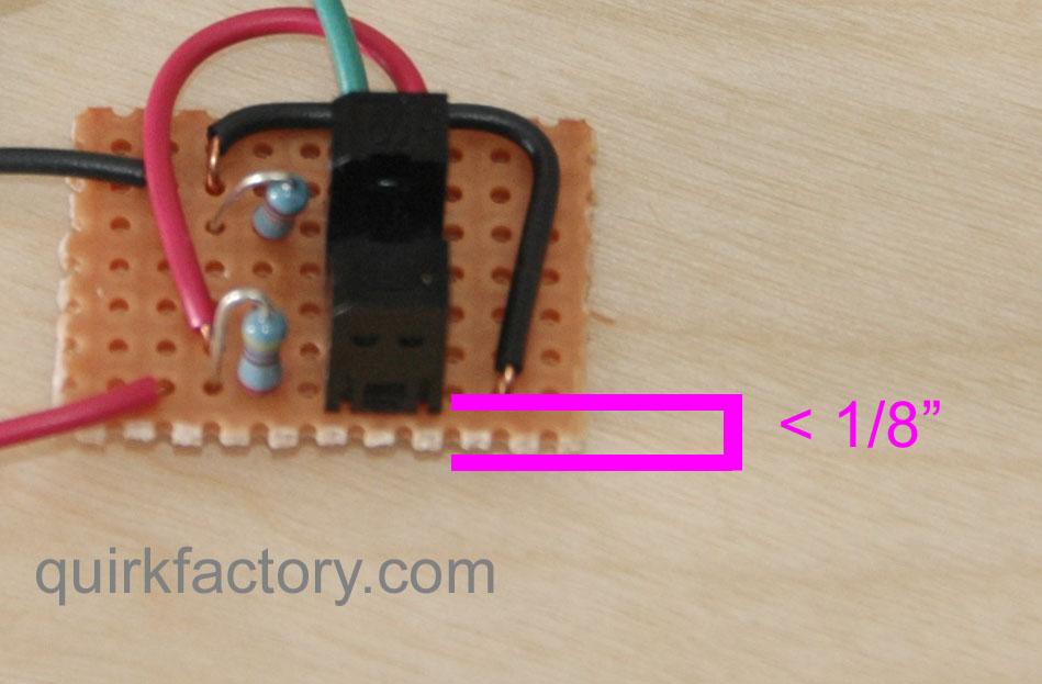
the final assembly looks like this. The red and black leads are for
+V and GND, respectively. Green carries the data out.
If constructing the sensors by hand on proto board,
the final assembly looks like this. The red and black leads are for
+V and GND, respectively. Green carries the data out.
 Note that the emitter side of the sensor must be aligned close
(less than 1/8") to the edge of the circuit board. In a later
step, we will glue a strip of plastic to the side of the sensor.
The plastic must extend below the edge of the perf board.
Note that the emitter side of the sensor must be aligned close
(less than 1/8") to the edge of the circuit board. In a later
step, we will glue a strip of plastic to the side of the sensor.
The plastic must extend below the edge of the perf board.
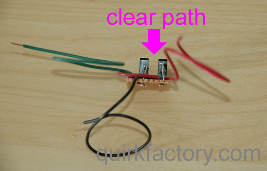
 Note in particular that the sensor and resistors must be aligned in a way
that allows a clear path through the sensor, as show in this picture.
Note in particular that the sensor and resistors must be aligned in a way
that allows a clear path through the sensor, as show in this picture.
Repeat
That's it - make seven of these, and test each to make sure that the
high/low output state changes when the sensor is blocked.
[Next: Step 2 - Laying out the Board >>]
|
|
|
 This picture shows the detail of the sensor circuits.
Note the alignment of the emitter and sensor parts of the
Sharp GP1S525
which are are labeled on its case.
This picture shows the detail of the sensor circuits.
Note the alignment of the emitter and sensor parts of the
Sharp GP1S525
which are are labeled on its case.
 If constructing the sensors by hand on proto board,
the final assembly looks like this. The red and black leads are for
+V and GND, respectively. Green carries the data out.
If constructing the sensors by hand on proto board,
the final assembly looks like this. The red and black leads are for
+V and GND, respectively. Green carries the data out.