| Project
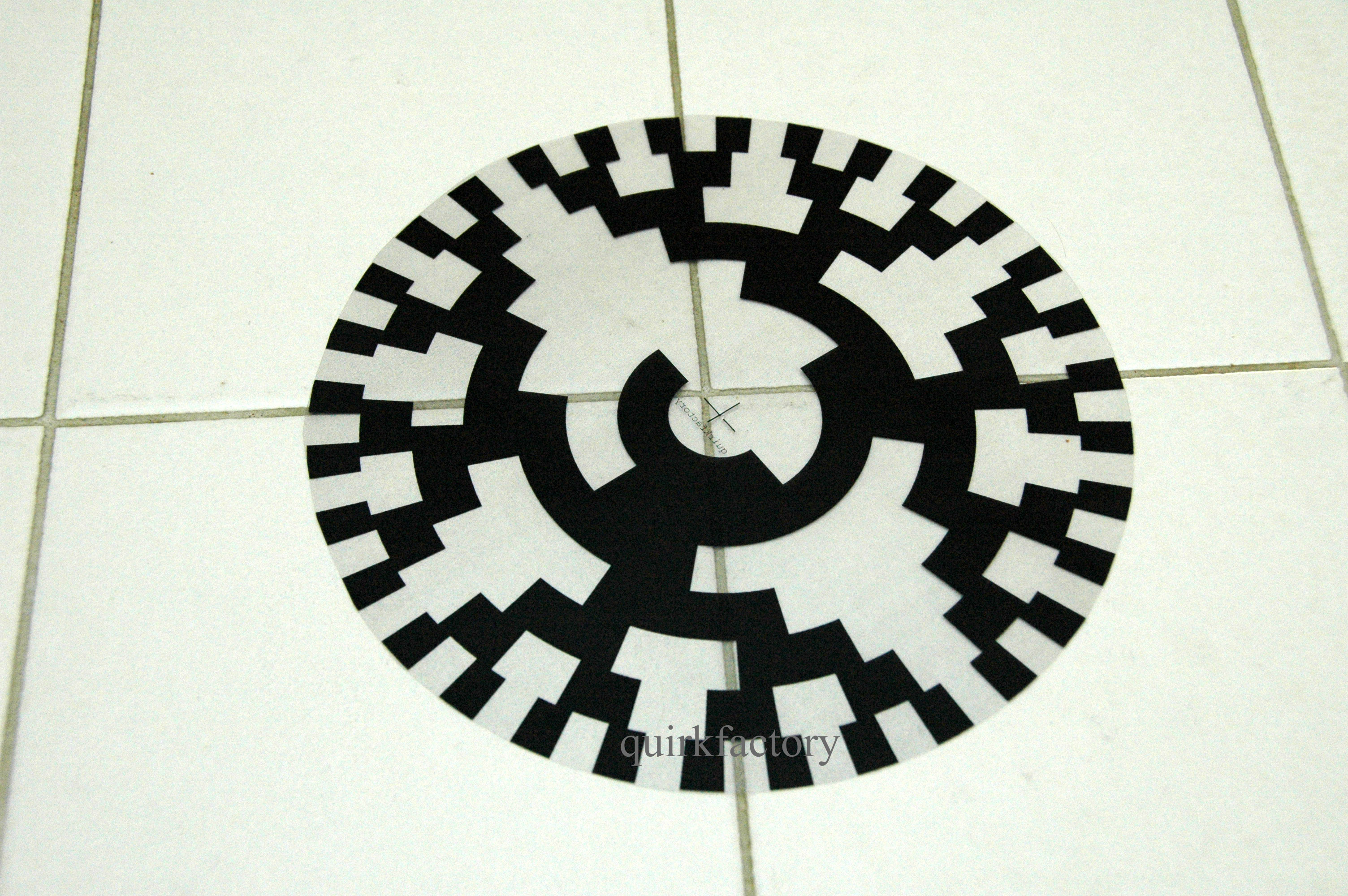
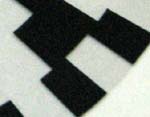
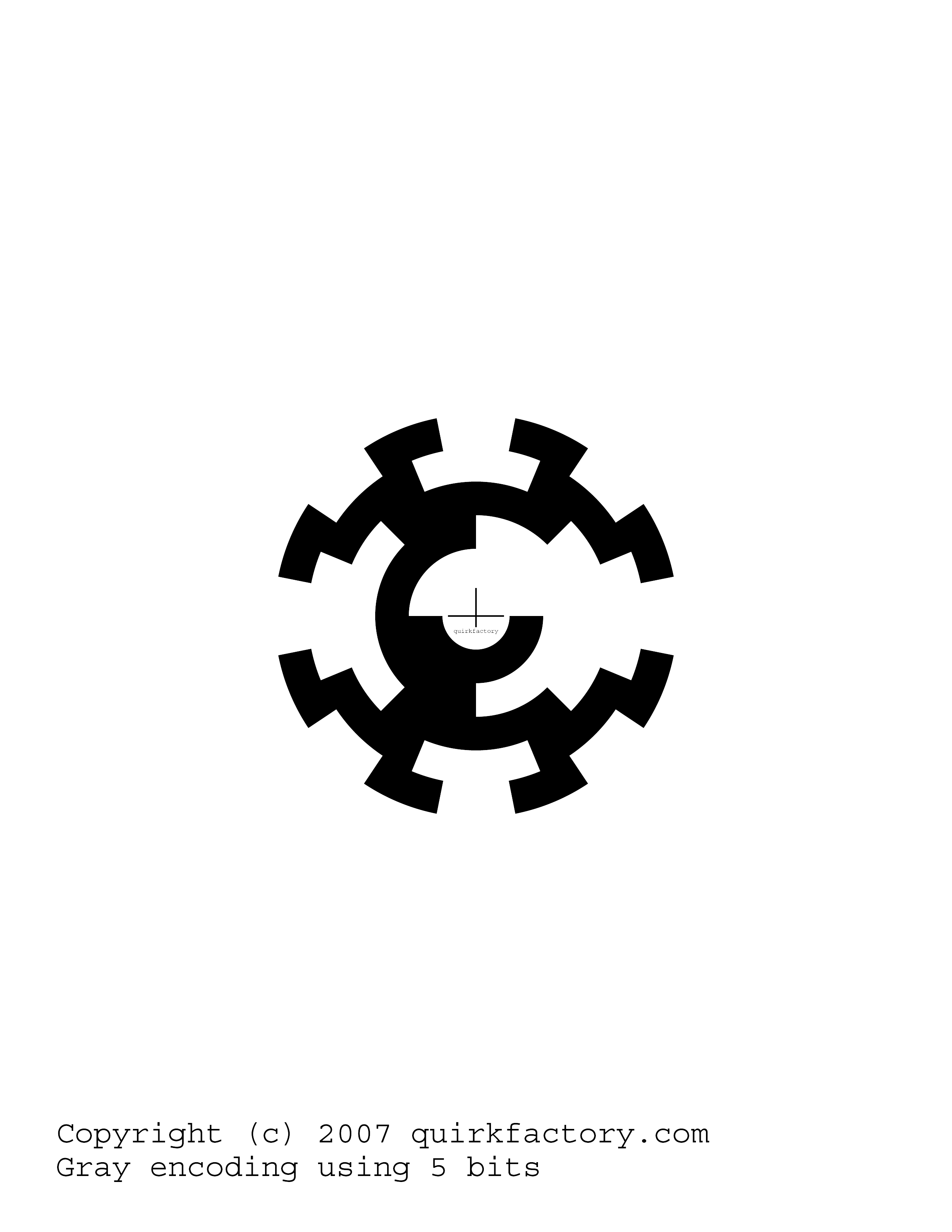
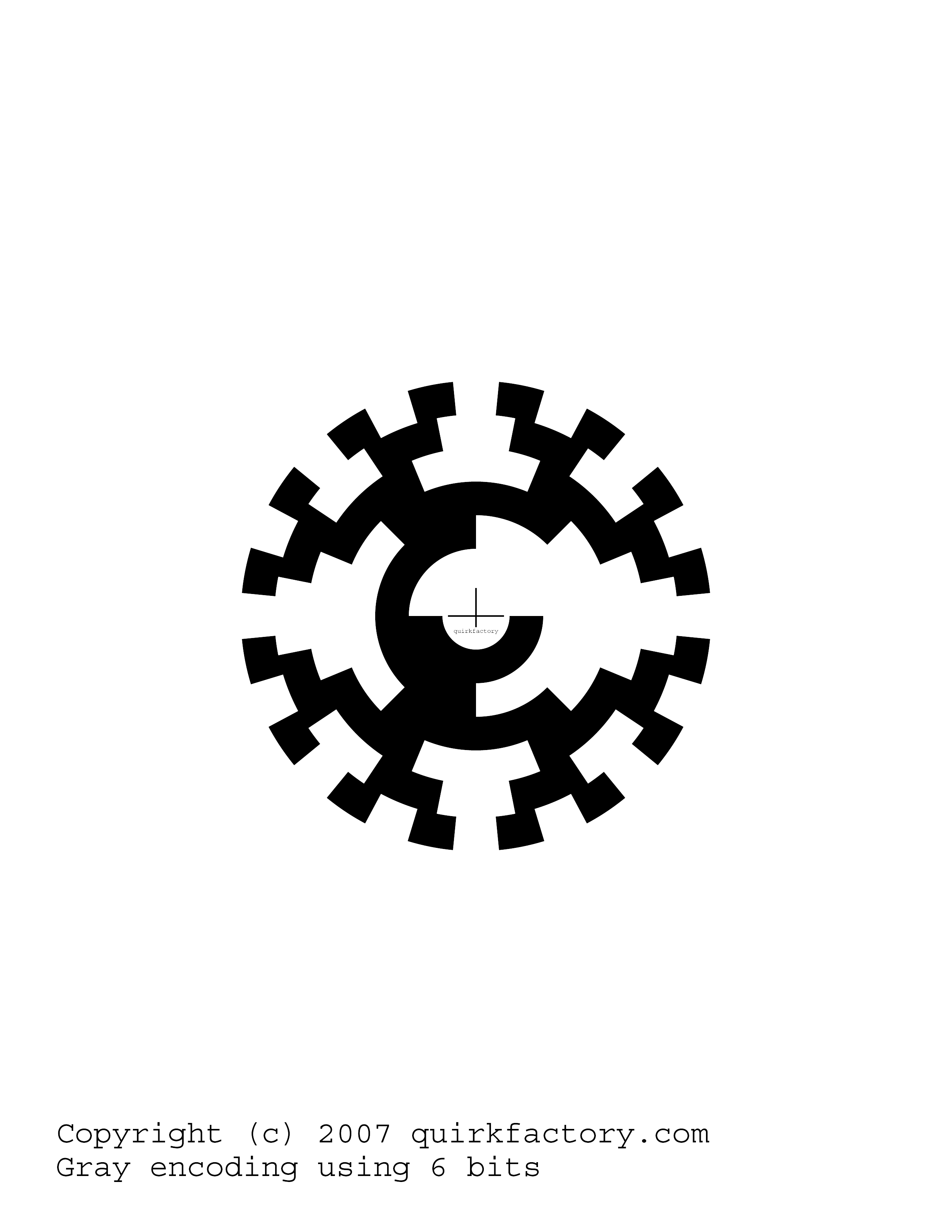
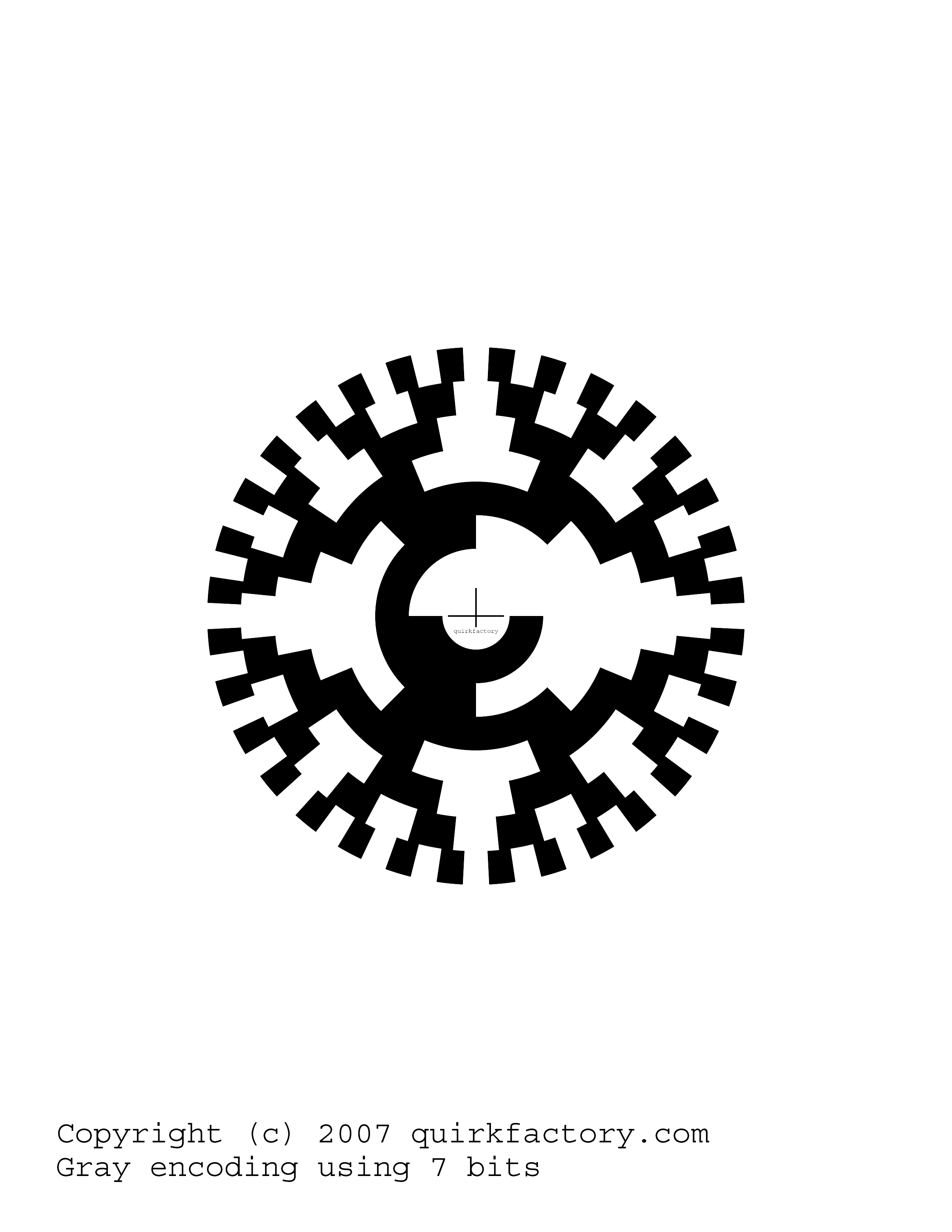
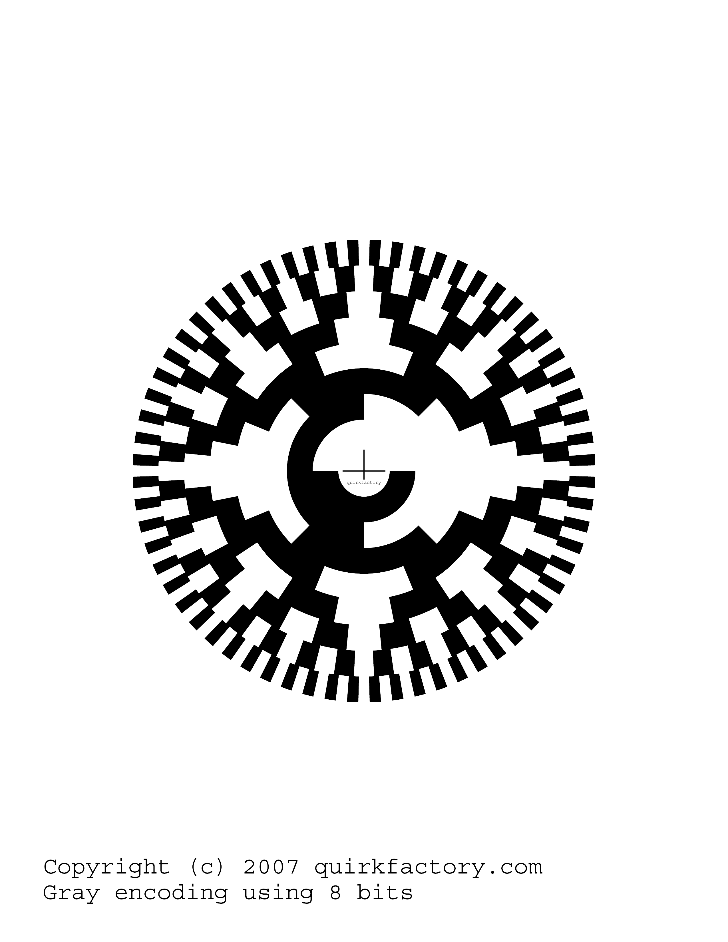
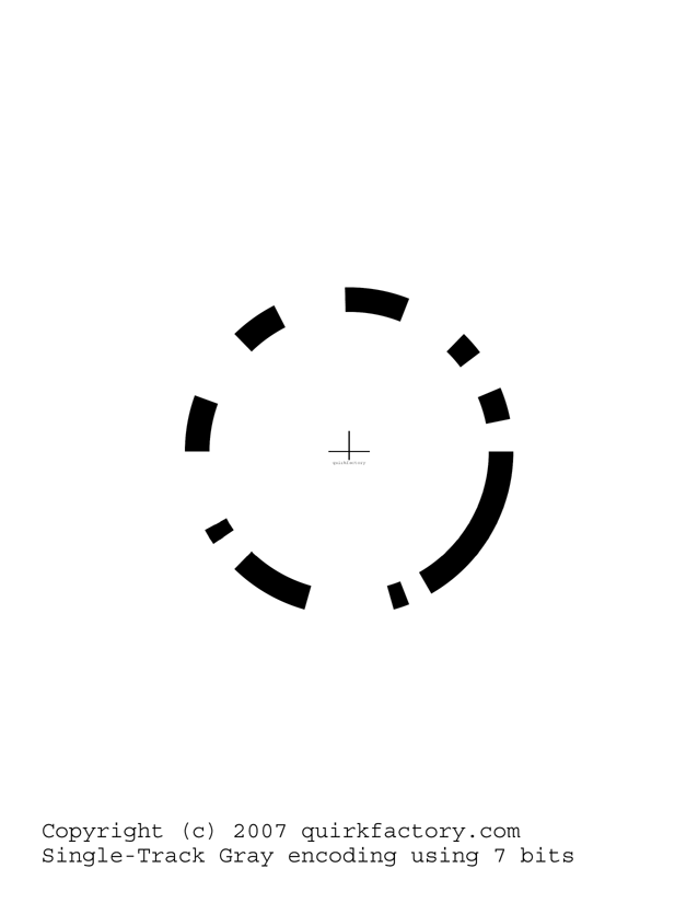
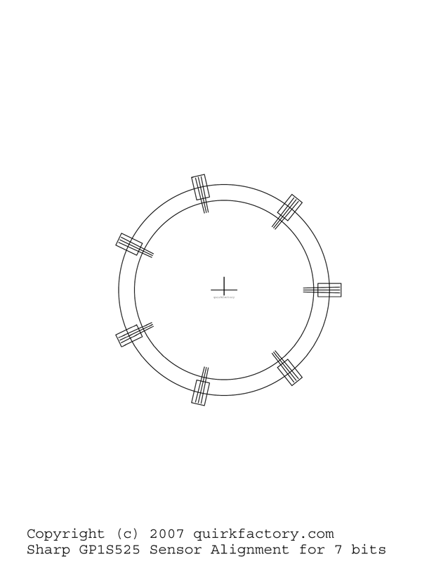
date: started July 2007. I wanted to build a do-it-yourself (DIY) rotary encoder (or shaft encoder - a device for measuring angular position, or linear position with a suitable attachment). That required making some templates that could be printed onto a transparent sheet, or printed onto cardboard stock and then cut out. The cut-out can then be sandwiched in between a number of optical emitter/detectors to implement a shaft angular position encoder. The circles are Gray Code laid out into a series of arcs, output as PostScript then converted to PNG using PhotoShop. The Gray Code program is available; just ask if you want it. Here's what the images look like (this example uses 5 bits): Here are the available images: Rotary encoders are useful in robotics and other automation applications. I naively tried printing a 7-bit pattern onto card stock paper, then cutting out all the black areas with an X-Acto knife. My idea was to use the cut-out as a template for spray-painting multiple circles. Well, it "worked" but the spray paint bled through too much in some areas, as you can see in this close-up: So instead I took the image to Kinko's where they printed it onto transparency plastic for $0.75US per copy. This technique doesn't have as high contrast, but I confirmed that it works ok with the photodetectors that I purchased. Here's what the transparency looks like after I cut away the borders: Here's a close-up showing the much-improved edges: I started assembling my shaft encoder, but the opto interrupters I had available were these Sharp GP1S525 CAT # OSU-55 from All Electronics: In order to place these radially around the gray code circle, I need to cut them apart, and then worry about re-aligning them. It occurred to me that it would be far easier to place them around the edges. Single-Track Gray Code This lead me to investigate and create a 7-bit single-track Gray code sequence. That looks like this [picture with sensor positions would be helpful] You can read a little more about single-track gray code sequences on the wikipedia Gray Code page. In this case you place the sensors equally around the edge of the disk, and need to carefully align the sensors. So I've got an image of the circle plus an alignment template here: The alignment template is specially designed to show the proper placement for the Sharp GP1S525 sensors. You'll also need this list of numbers to decode the sequence. [I still need to add more detail here] |


